Tubeless Wheels
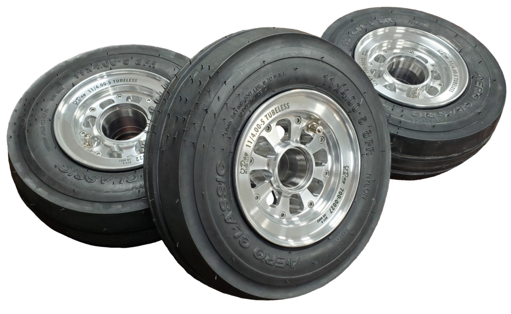
There are a few wheel options for the 320 and 360 Lancairs. The original design used Matco wheels and brakes but Grove and Beringer also make their own unique replacements. I had considered purchasing Beringer’s product, since it eliminated the tube, but with a cost well over $3000 at the time, and more today, I decided that money could be better put toward other improvements on the plane. This decision didn’t fix my original wheels however so I decided to design my own.
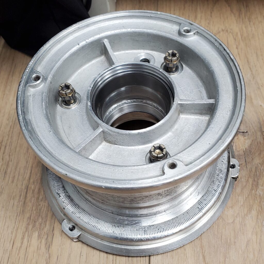
My original Matco wheels might have been savable, but I didn’t want to mess with them. There was significant grooving on the sealing surface due to two factors: First, the bearings had been allowed to run without the proper preload, and second, the bearing seal applied too much pressure on the sealing surface generating excessive friction between the seal edge and the bore of the wheel. I first noticed this when attempting to adjust the preload on the tapered roller bearings, the friction was so high that it was difficult to determine if the proper preload was applied. This is a problem that I think was limited to older Matco wheels as newer ones appear to be machined with a slightly larger seal bore, a trick I integrated into my design.
New Design
The primary goal on the custom landing gear for 320ED was to improve its performance at absorbing and releasing energy. The wheel and tire plays an important role in this equation so obviously I wanted to improve this area as much as possible. First, some background to understand the technical challenge:
There are two main gear tire sizes available on the Lancair 320/360, the “standard (small) gear” and “outback gear.” Of these 320ED uses the standard gear with three 11/400-5 tires. This is generally taken to be an inferior design when compared to the larger tired outback gear and from a shock absorbing perspective it certainly is, but, neither design is particularly good. The primary advantage to the small gear is that the tire is small enough to fit within the wing without any bulging of the gear doors. This bulge is unavoidable on the outback gear and results in some added drag and difficulty sealing the gear door. The significant advance of the outback gear is two fold 1.) the lever arm of the fork is larger which allows more travel of the gear, and 2.) the physically larger tire allows for more compression under load and a higher load capacity. Both gear designs are somewhat unique in that they have very little landing gear travel (1-2″) which, besides translating higher loads to the structure, results in the tire absorbing larger loads then intended by the tire manufactures, fully compressing it.
Another point to consider is that the standard gear’s 11/400-5 tire size was never intended for use in aviation, but had made its way into the experimental market due to its convenient size and low cost. The most popular of these tires, the Lamb (CHENG SHIN) has optimistic load ratings between 209lb (2 ply) and 475lb (8 ply) and requires a tube be used. This load rating is obviously inadequate for aircraft with gross weights between 1600 and 2000lb like the Lancair 320/360. (EDIT- It was explained to me that the Cheng Shin was designed to be an aircraft tire from inception so it is different from the many other industrial tires)
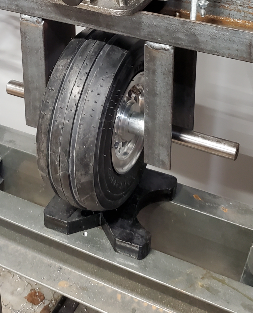
While it is normal for aircraft applications to significantly compress the tire under high load, the problem is that when you couple the high loads due to the lack of landing gear travel with the insufficient load rating of the tire you start finding that the tire compresses so much that it pinches its side walls together between the wheel rim and runway. This can be replicated in a load test:
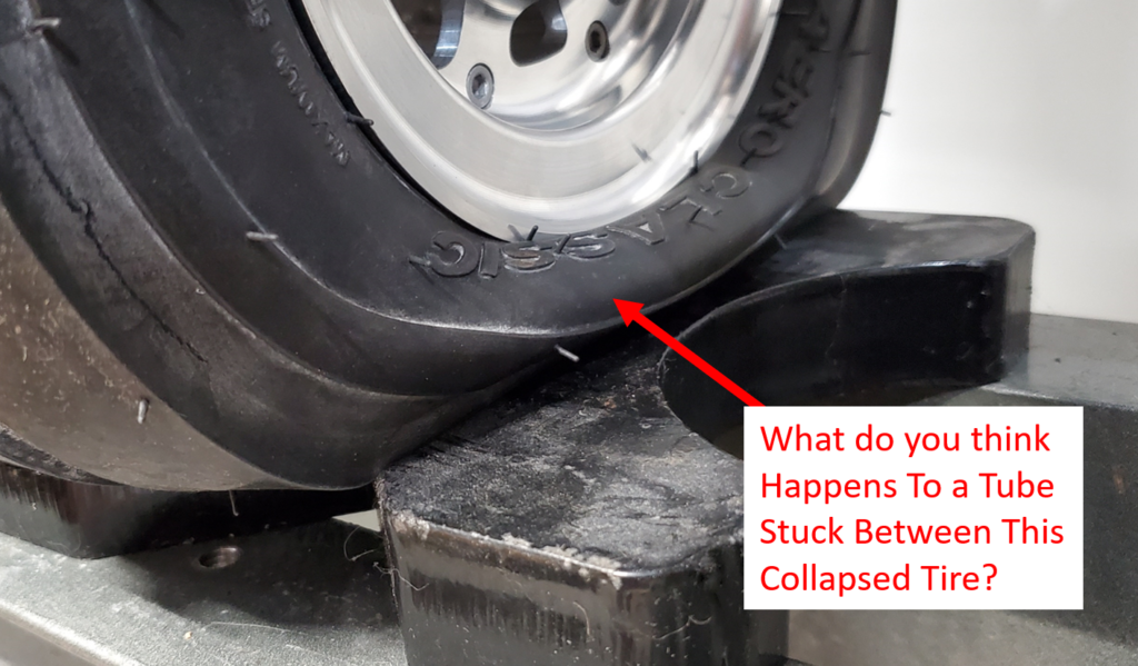
The image above is not of a flat tire, this wheel assembly is fully inflated but subject to the applications limit load. The tire and wheel can survive a certain number of these complete compression events but the relatively thin tube inside the tire cannot and it is often punctured by pinching of the tire. This this a common issue on the Lancair 320/360 standard gear aircraft.
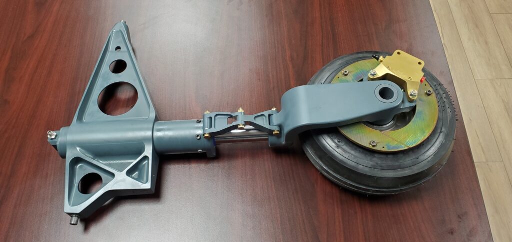
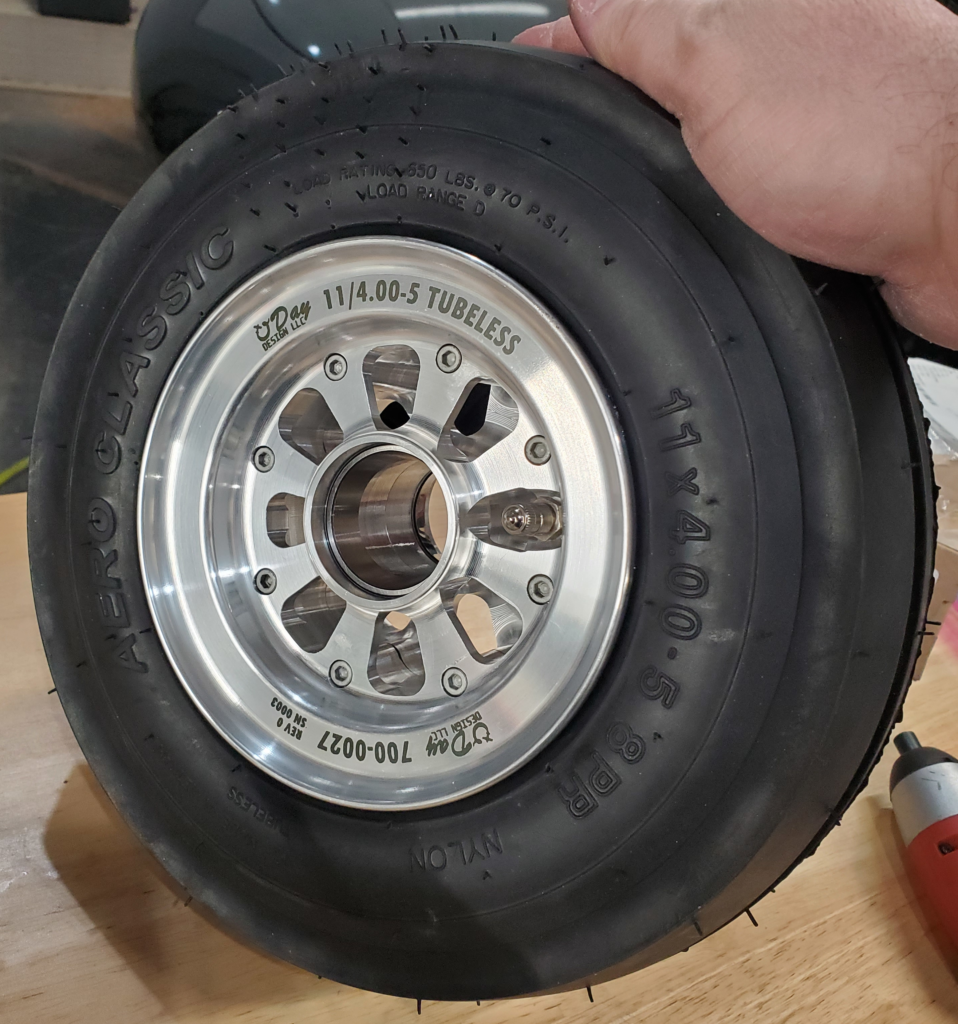
To solve these problems on N320ED I developed a new landing gear and wheel. The landing gear, which I will cover in another future post, increases the travel to 4″ which significantly reduces the loads on the gear, airframe, and tire. The wheel design I developed completely removes the tube and uses a tubeless tire, the Aero Classics DTR5582, which has a load rating of 650lb. This rating is somewhat marginal when compared to certified applications, however coupled with the increase gear travel it is a significant improvement and is the best available option for this size. The big advantage to using this tire and not going to the larger “outback” gear design is that it does not require a drag inducing bulge in the gear door to fit in the wing. In fact, this gear design incorporates enough travel that it is superior to the outback gear in absorption capability despite using the smaller tire. . . somewhat of a Win-Win
I had a few other goals with my wheel design:
- Reduce weight
- Prevent damage to the tire due to the bead when fully compressed
- Be able to use original Matco brake, bearings, and axle components
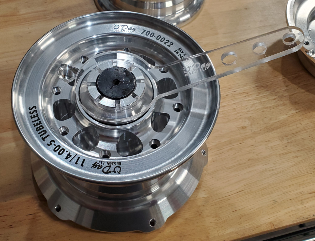
- Improve the looks of the wheel as it is exposed in this application
To start design I took measurements and a 3D scan from some Matco wheels to determine the locations of the bearings and brake disk to ensure it would be compatible. Since I was machining from billet my base material was much stronger then the cast Matco wheels and I was able to shave out some weight. This was an iterative process where I attempted different weight saving strategies and used an FEA analysis to validate the results. I was very happy with the analysis as I was able to combine nitrogen pressure loads from the tire with compression landing loads. The results of this was later validated with static load tests on the finished assembly. The FEA analysis also considered fatigue strength, I have considered building a dynamic tester to more thoroughly validate this aspect but for now I think the initial design is acceptable for my own test flights.
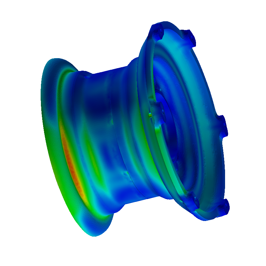
Determining the bead design was an interesting experience. I reached out to the Tire and Rim Association to determine what bead design was used. While they were extremely helpful, it turned out that it was not documented with them and was custom by the manufacturer of the tire. Knowing this I ended up 3D scanning the bead to help determine the optimal profile. I was concerned that it would take multiple iterations of the bead design to get a good seal, costly considering the material and time to prototype these, but that did not turn out to be the case. My first design worked flawlessly only after finding that one of my hairs had become stuck across the seal, sabotaging my initial leak test. Currently the tires have been inflated over a year without considerable leakage.
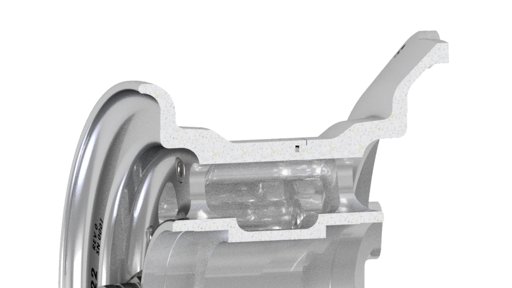
I tested the wheels to their limit load using a custom fixture in my press which is modified with a pressure gage to allow me to measure the force applied. The first wheel I tested (shown in the earlier picture with the distorted tire) performed fine, but I noticed that the somewhat sharp edge of the tire rim could be more blunted to reduce the point load on the sidewall of the tire. To improve this I changed the rim design slightly by enlarging and blunting this area as shown in the above image.
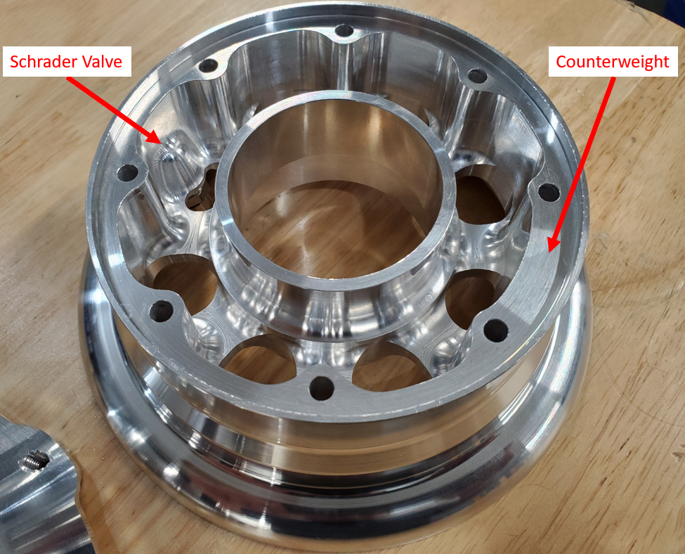
Besides pressure, landing, and fatigue loads, there were a number of little details that I had to address. One of these was adding a counterweight to offset the weight of the Schrader Valve and boss. I designed this in CAD so that the wheel (alone) is perfectly balanced.
Another feature is the special axle nut I made out of out of a 7000 series alloy. It uses a custom wrench that locks into the cotter pin slots. Since the torque on this nut is super low the tools can be made out of cheap, light weight, materials such as laser cut acrylic allowing me to keep the wrench in the plane all the time. The axle on my gear is hollow steel, lighter and stronger then the original aluminum shown below, and so galling of the two materials is not as much of a concern.
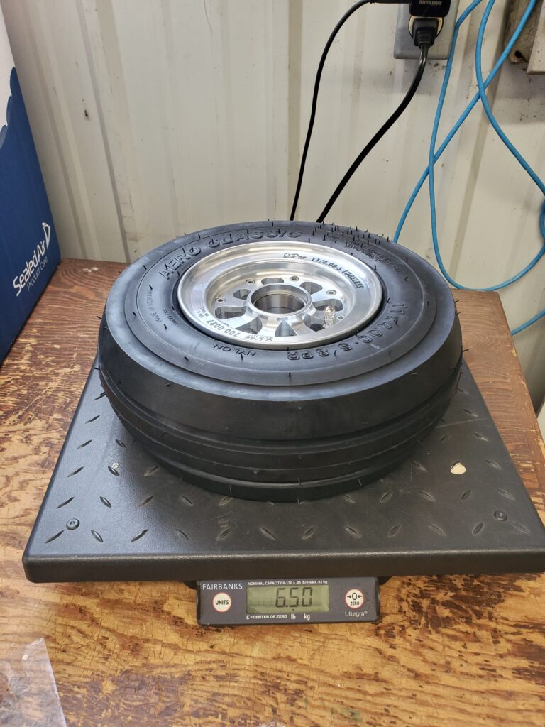
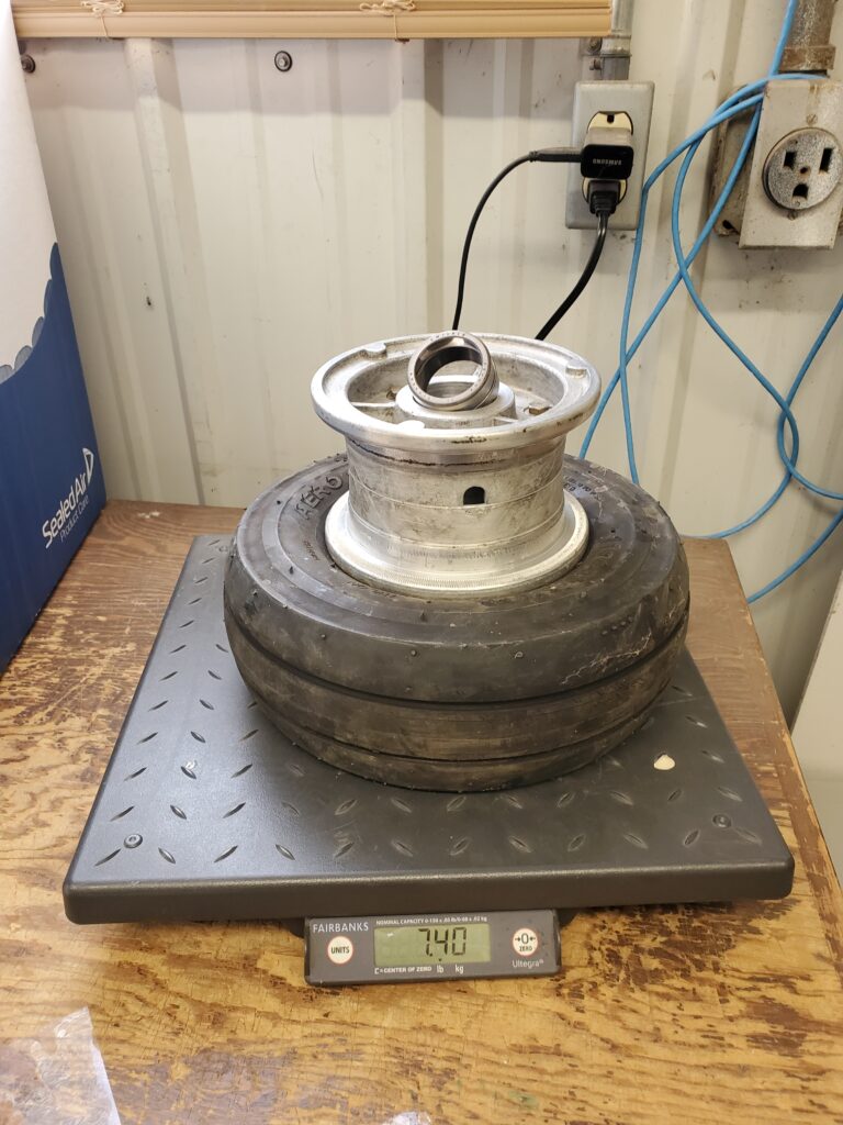
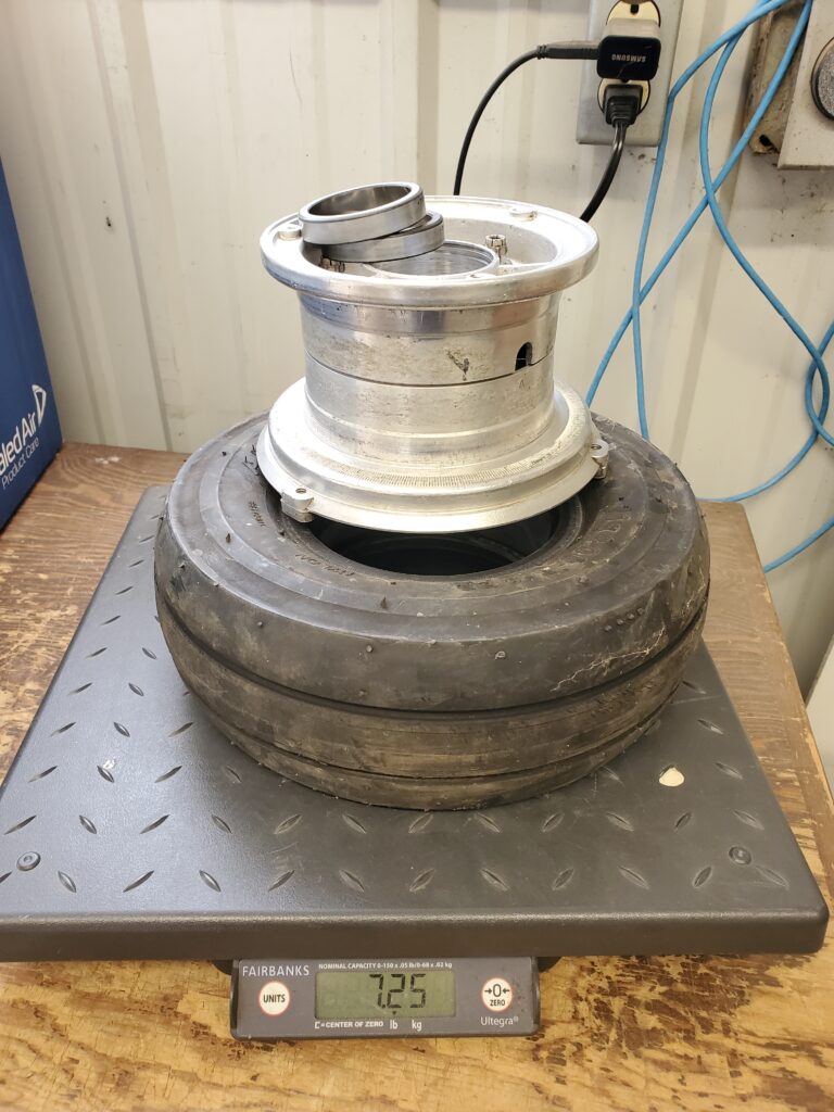
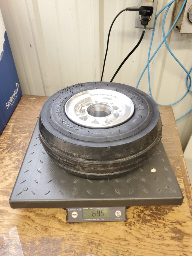
The new wheels save approximately 1.7lb total.
Manufacture
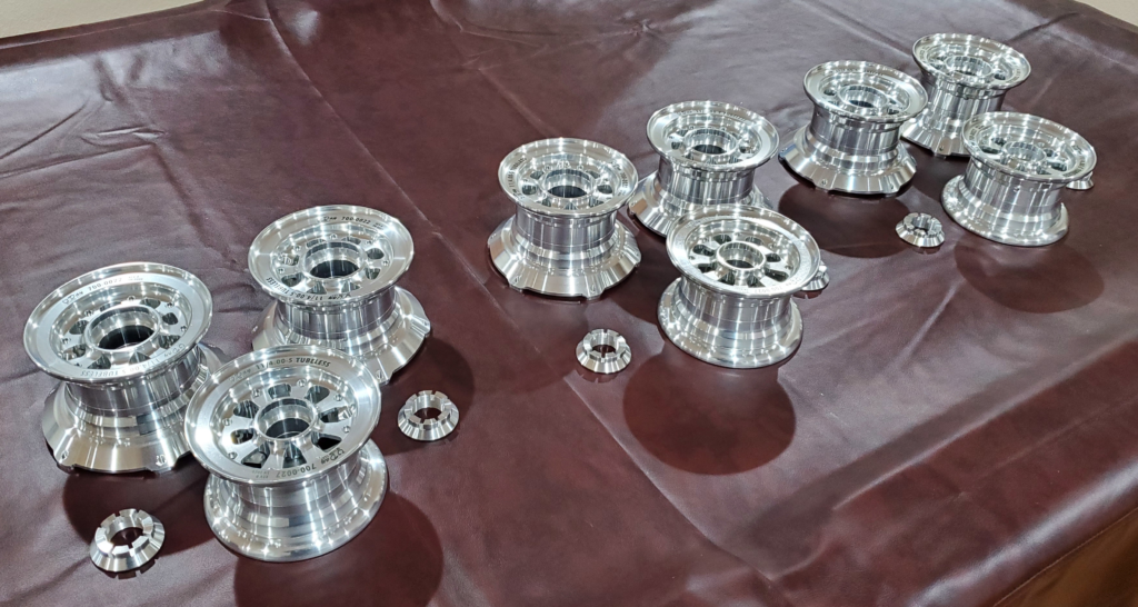
Manufacture of the wheels was a new experience. I had just begun learning how to use a new CNC lathe at work and these wheels turned into the ultimate crash coarse as the parts were at the upper limit of the lathe’s capability. They were so large that I had to disable the tool setter to gain the clearance I needed for the custom jaws I made. This machine also has live tooling which allowed me to do most of my milling operations in the lathe. Ultimately some of the finish work had to be done on a CNC mill.
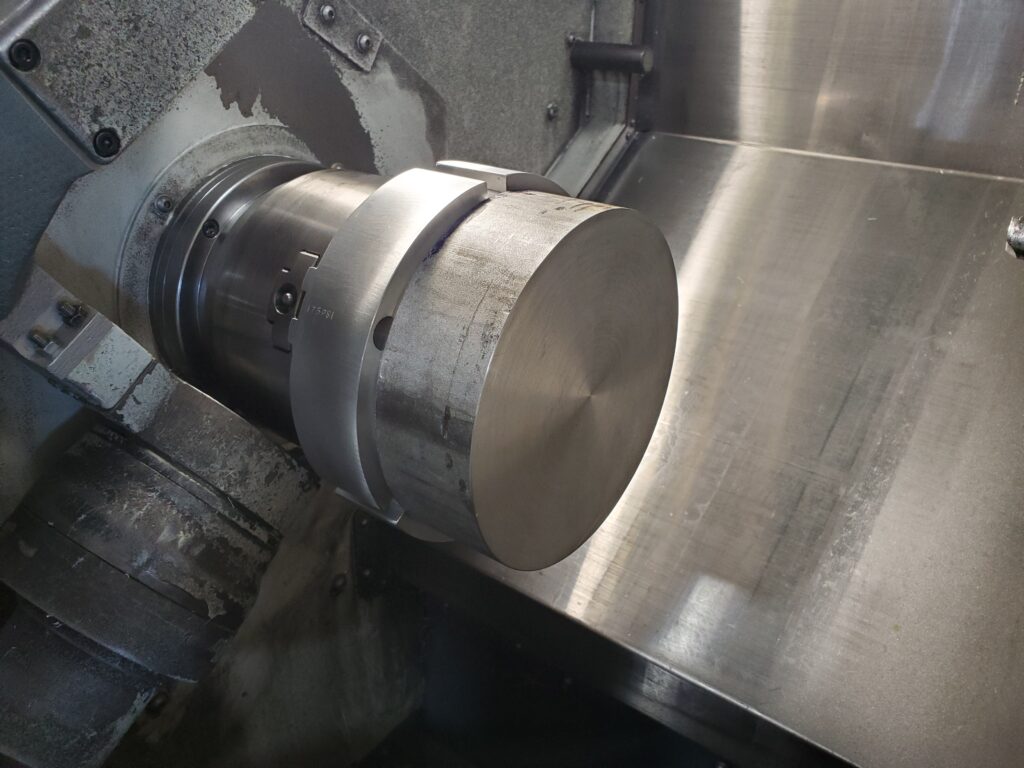
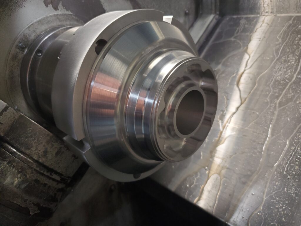
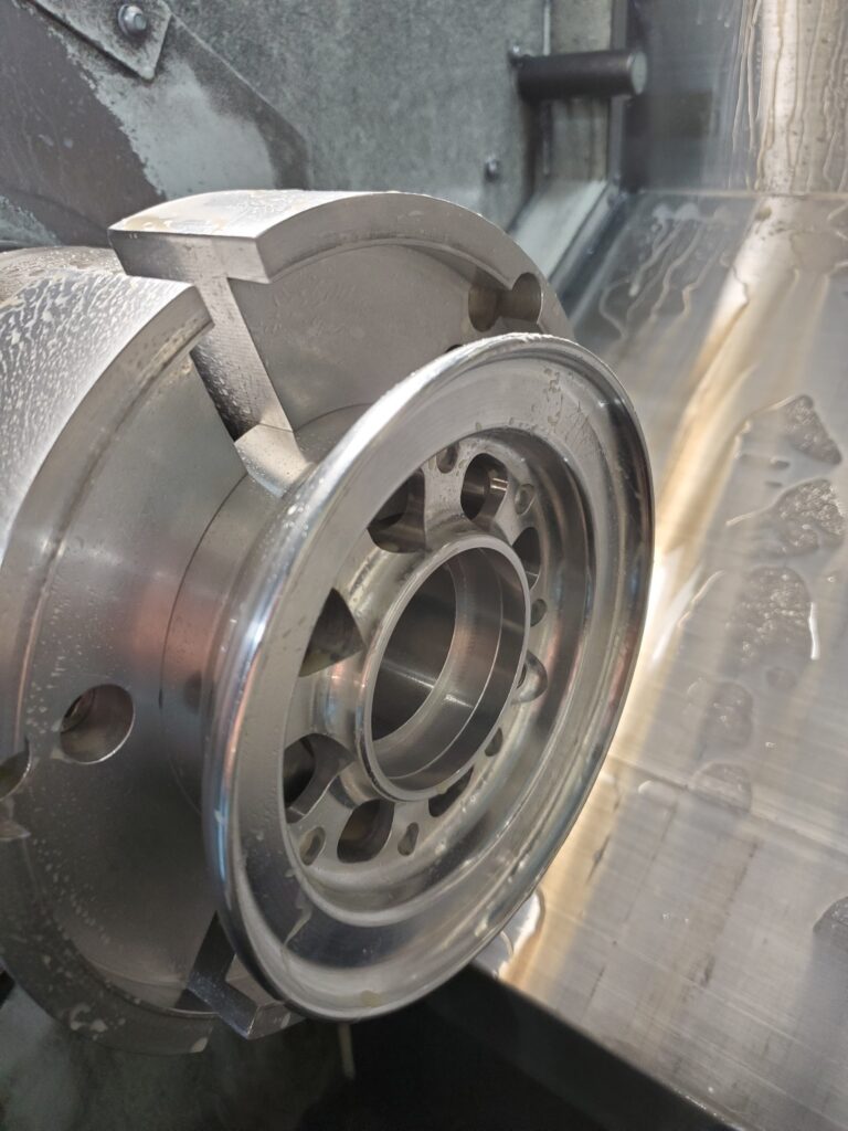
To finish I laser marked the wheels and clear Cerakoted them to prevent future oxidization. No hand polishing was performed here, its all in the feeds, speeds, and tools selected.
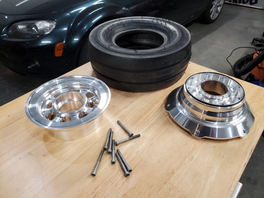
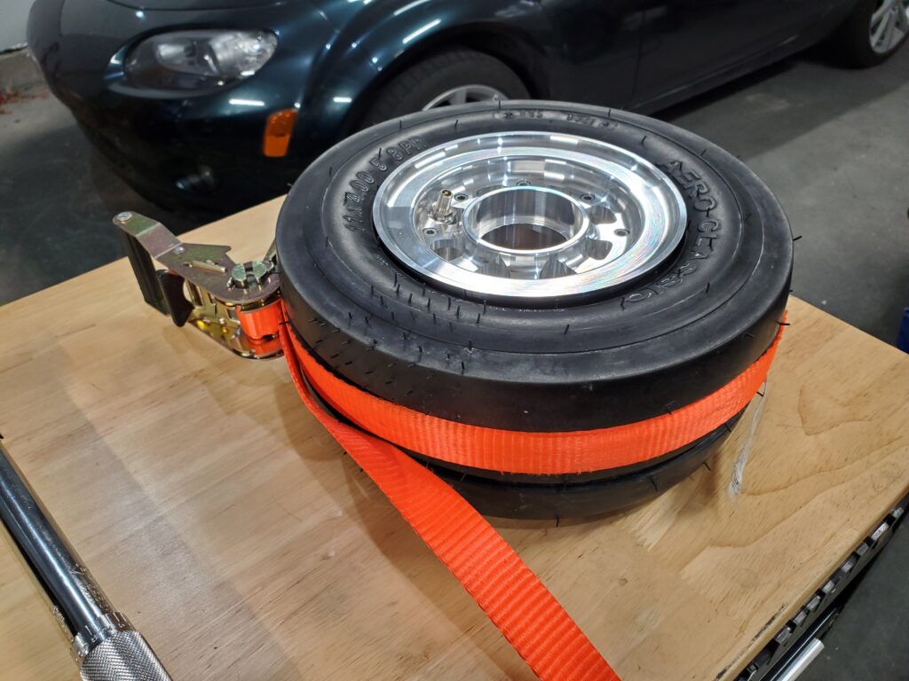
My wheels assemble using socket head cap screws and are sealed with an O-Ring in the center. The seal design I chose is very robust to flexure of the two wheel halves under load. This was another area that the FEA was helpful in and the results speak for themselves, my wheels didn’t have any detectable leakage during or after load testing. This design is also very easy to assemble, requiring only a ratchet strap to initiate the bead seating as air is initially applied. Disassembly is even easier, just remove air pressure and unbolt the wheel halves, they simply come apart.
For those who wish to acquire a set for their 320/360, I am not ready to sell them until I have proven them with more tests and have a way to make cost effectively, but you are welcome to reach out and tell me if you are interested. It would be very helpful to me to understand how many owners would be serious and how much a set would realistically be worth.

Beautiful work, Shane.
I will be interested in multiple sets if you count the other builders that I advise.
Thanks Bob, That’s great to hear!
I’m interested Shane! As always excellent article/write up on the process and design.
Regards
Darren
Thank you Darren!
I would be interested in replacing the wheels on my IV.
Interested in a set Shane.
RJ
I would like to buy a set of main wheels for my Lancair. When would it be possible ?
Geir Kvam
Trondheim
Norway
Great article Shane. It sounds like you’re able to improve the quality, reduce weight, and make them look better all at once!
I would be interested for N8YH (360), if the price is right. Keep me informed if you’re ready to go to market with these!
Shane put me in for a set. Great idea. Hopefully it’s easy to overhaul the seals as well. We’ve sure come a long way from the old donut style shocks. I just ordered your new GM4s as well.