Nose Drag Brace
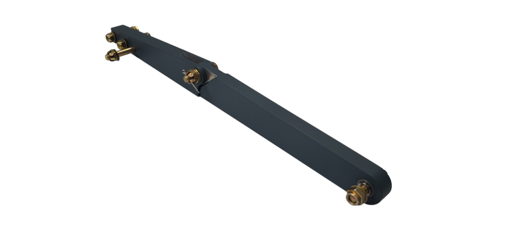
I manufactured a new GM026 drag brace for N320ED and have gotten many questions about both the existing design and the changes that I made. Basically, this linkage shares the same geometry as the original but has been improved in the following ways:
- Addition of shaft and bushing at strut attachment joint (similar to Randy Snarr mod)
- The use of 7000 series material (improved strength)
- Quality Improvement
To understand more specifically how these changes improved the assembly I need to explain what problems I found with the original linkage.
Strut Joint Improvement
The first disappointing part of this design is the use of the bolt as a pivot point on the strut end. This allowed rotation of the bolt inside both the linkage and strut bracket holes. I personally didn’t like this since the strut is so expensive and the thin bracket hole could become enlarged over time. On my strut the hole had only a little wear but the bolt had a lot and was also slightly bent.
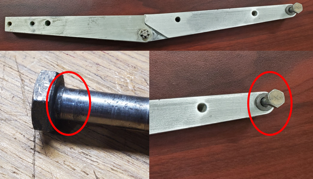
To combat the strut end pivot wear I took inspiration from a linkage made by Randy Snarr who added a bushing and shaft to this joint. The shaft being firmly clamped between the flanges of the strut so that rotation only happens between the shaft and bushing.
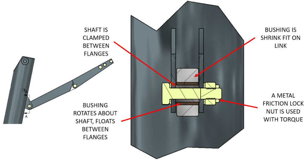
My design does differ slightly from Randy’s. I increased the cross section of the link itself to stiffen it, used a thinner wall thickness around the bushing, and used a harder SAE 863 bushing pressed into this end with a ground 17-4 stainless shaft that is attached to the strut. I’ve used this material combo on certified applications before where the load is high but rotation speed low, and it performs excellent. The bushing is simply replaced if worn.
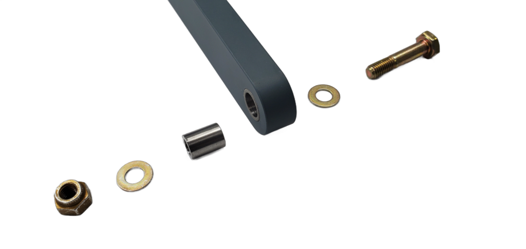
The bushing is installed into the linkage housing using a slight shrink fit so it does add hoop stress to the linkage. To compensate for this I added wall thickness, but not quite as much as Randy’s design. I validated this change using FEA and ultimately a load test where I loaded the link in tension using loads derived from 8.10.2 of ASTM F3116 (Part 23 nose gear requirements). This condition places a force on the strut in the forward direction with a large vertical component like shown below.
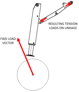
Doing the geometry and math, 8.10.2 leads to an approximate limit load loading of 2250lbf in tension on the linkage. I built a fixture for my press that oriented the linkage correctly and slowly loaded the linkage to this load and backed off to inspect for permanent deformation, none was found so I continued to 1.5X this load (3375lbf), with no signs of deformation.
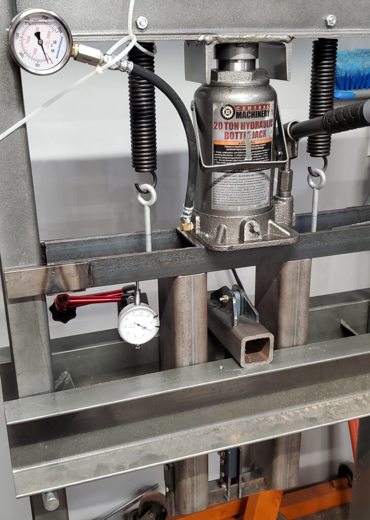
I decided to load the link to failure:
This resulted in the link-to-link pivot joint failing where the bolt was bent, outer flanges distorted, and the bolt torn out of the center pivot hole.
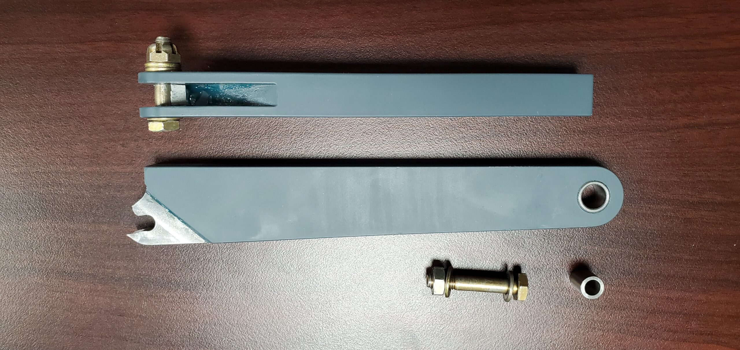
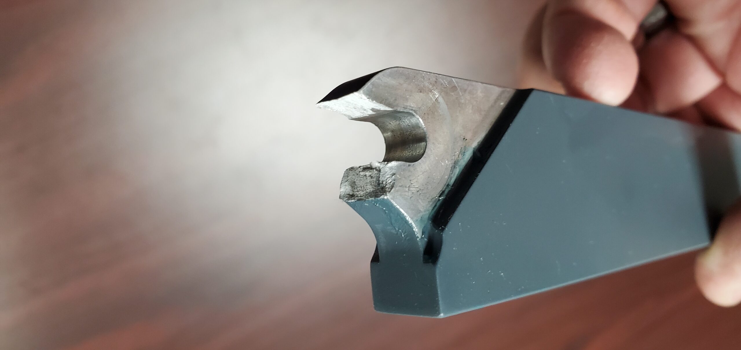
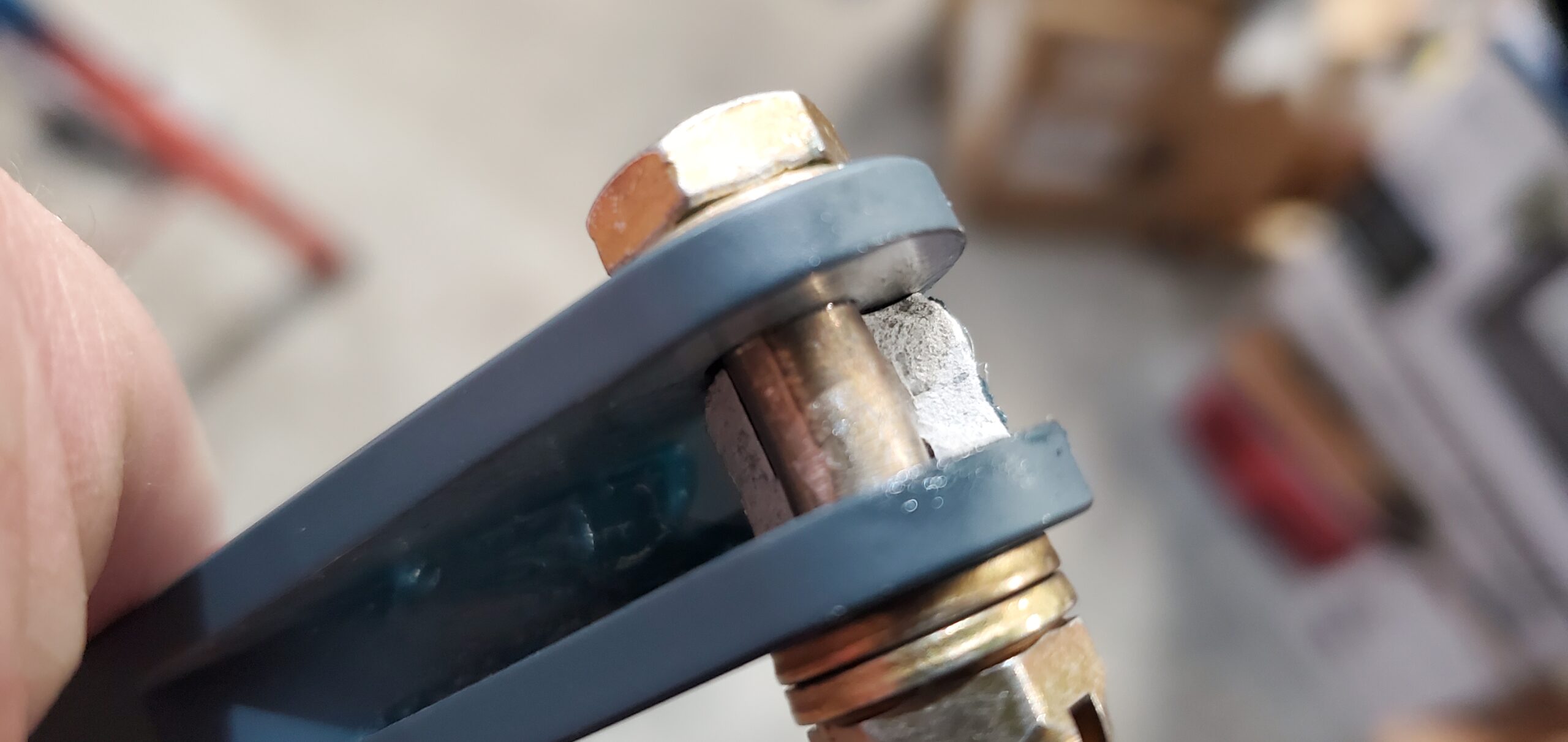
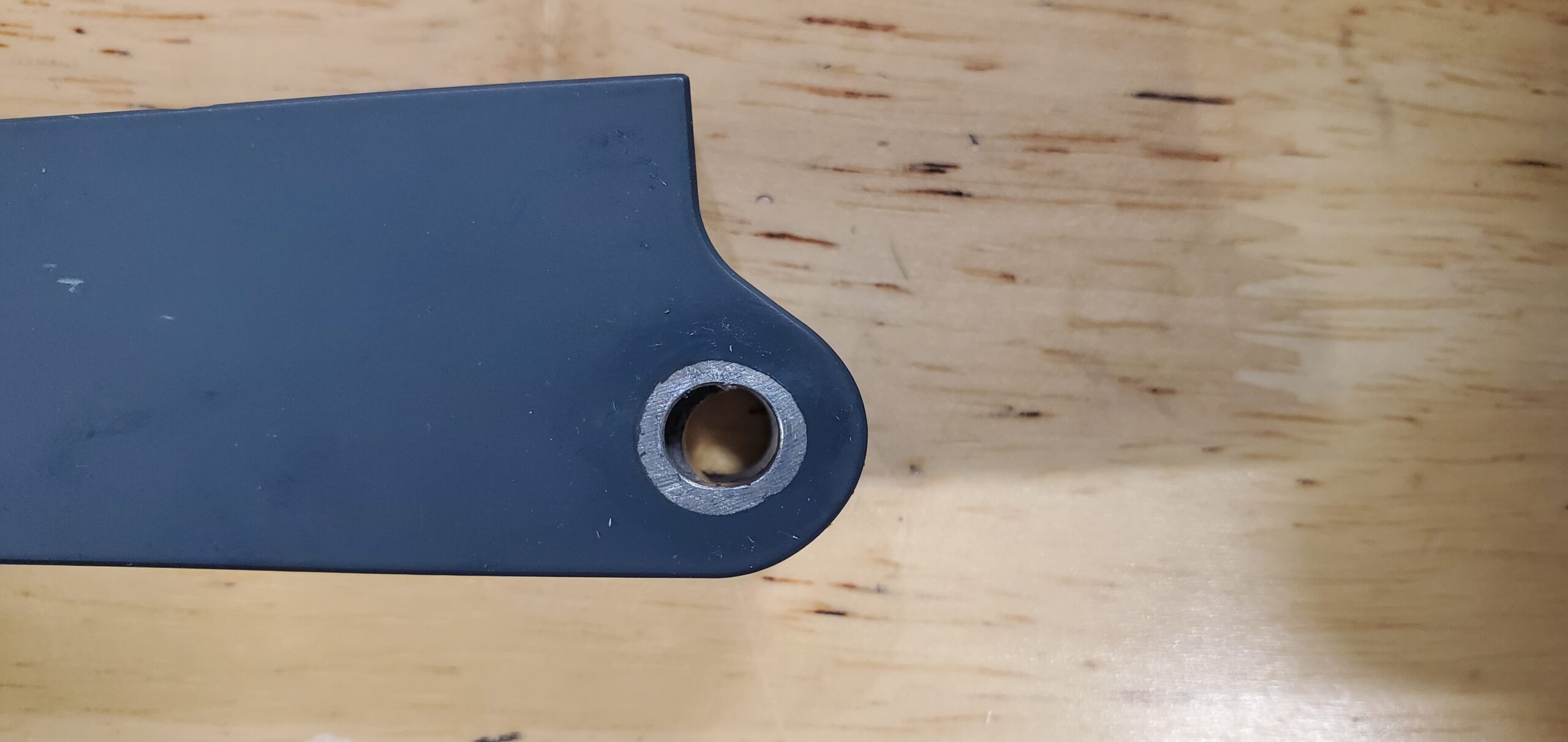
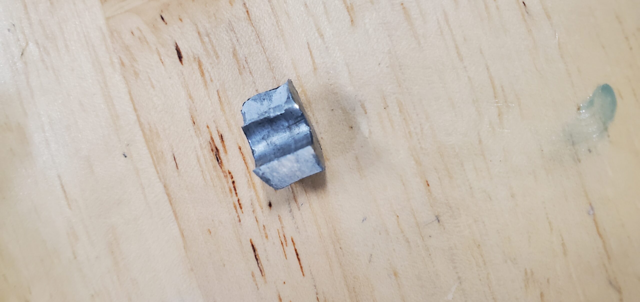
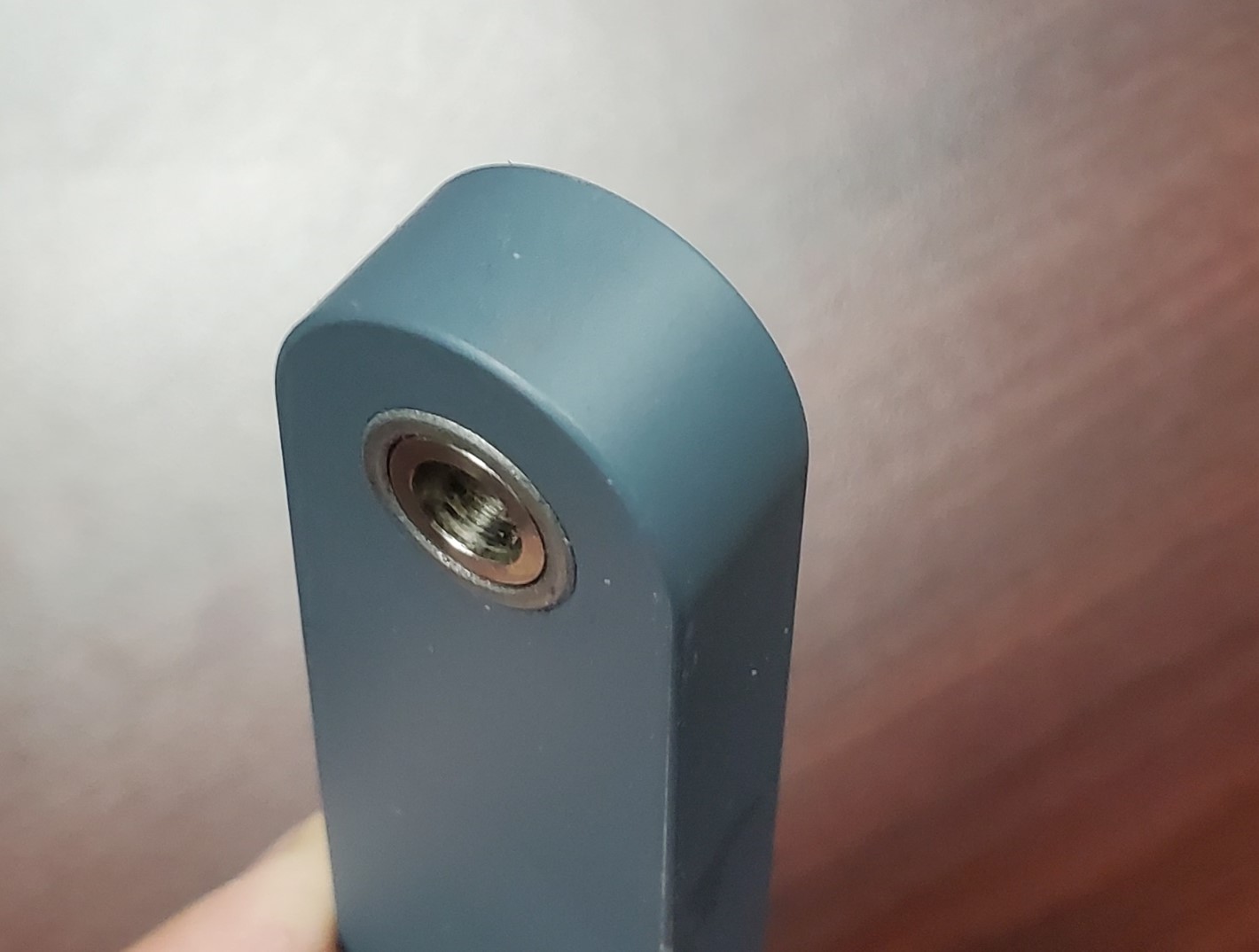
However, there were no indications of this load affecting the new strut pivot joint. This joint remained elastic with no perceivable change to the bushing fit, cracking, or bending of the bolt used to attach it to the strut.
I had setup a simple measure of strain using a dial indicator and was also able to determine approximately both the yield and ultimate load strength of the linkage in tension. I was quite surprised how good this data looked considering the crude setup:
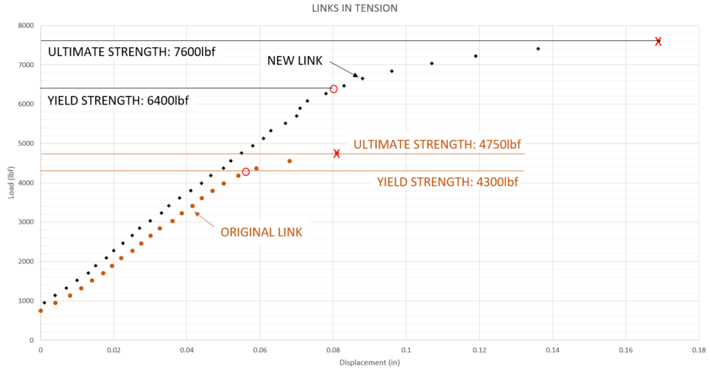
Note that I also tested my original linkage assembly which failed in a similar method. Here the strength difference between the materials is readily apparent. Not only is the 7075 alloy stronger but it also allows for more plastic deformation before failure which might make detecting an issue with an overloaded link easier.
So, what does this tell us? Well, the new press fit bushing design is sufficiently strong as it far exceeds the strength of the pivot joint. The clamped shaft design is also far superior in transferring load to the strut bracket as the clamping AN4 bolt did not bend despite the AN74 pivot bolt bending significantly, both having a rating of 7360lb in double shear.
This also brings up a good point, that this linkage is now about as strong as it could ever be as the bolt rating has been reached. Since the flex of the bolt contributes to the failure, I believe further improvement could be made by using a stiffer, hardened, pin in place of the AN74 bolt. I actually made a design for this pin, using snap rings on either end, but have not produced any.
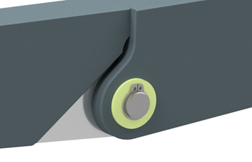
The link yielded at a load of 6400lbf which offers a design factor of approximately 2.8, meaning it exceeds the requirements of the ASTM specification for the forward load. The original link also met this requirement which I was quite surprised by.
Material Improvement
The second issue with my link was that it had yielded significantly at the over center stop. This was caused by compression loading from the nose wheel touching down, the tire spinning up, and from impacting bumps or objects on the ground. I have seen similar yielding on other 360s but I do not know how common it is, my gear had a rough life so it probably fared worse than average.
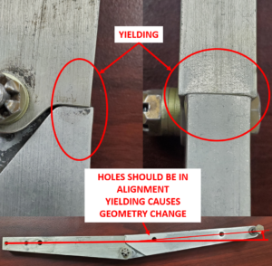
The yielding on my original linkage was significant enough that it affected the geometry, which further increased the load on it as it pushes the linkage more over center. While not at ultimate failure yet, if the geometry is allowed to change too much the leverage due to bending of the linkage would ultimately fail the pivot joint and likely pull the hydraulic cylinder out the top of the gear well. It’s also possible for the gear well attachment pivot, GM27, to become damaged as the reactionary loads placed on it also become quite large.
Another thing to consider when discussing yielding of this joint is subsequent loading events. Assuming properly adjusted hydraulics, if damage is done to the over center stops an air gap may develop between the stop surfaces. This will allow the stops to hammer together causing a much higher load to be imparted on them. It is therefore important to check this joint periodically for yielding, any sign of a gap between the stops, and the hydraulic rigging.
My original linkage was made from 6061, likely -T6 which has a yield strength of 40ksi. Based on discussions with other owners regarding the main gear over center links its possible some of these could be 2024-T3 which, with a yield strength of 50ksi would be slightly better that that of the 6061 version. I made my new links from 7075-T7 since I had some laying around, although if I make again, I may use 7050-T7. These materials have a yield strength around 50-70% higher than the original 6061-T6 linkage. This harder material will better prevent yielding at the joint and buckling under compressive load.
Wear inside the pivot holes will also be less with this material. I had considered a hardened shrink fit 4140 or tool steel bushing setup similar to Chris Zavatson’s 17-4 bushing in his main gear linkage, but this would have required a number of changes to the overall size of this joint to allow it to maintain its compressive and tensile load carrying ability. I may add this in the future now that I have a testing fixture and can try a few iterations, its a great idea but I’m not sure it’s necessary. My original linkage had around 1200hrs but only had a little wear, most of that appearing to be distortion from overload event/s.
In service the linkage is subject to both rearward (compression) and forward (tensile) loads due to landing conditions, spring back, and towing. Once retracted it is also subject to G-loads on the struts, but the forces involved are much lower than those that react with the ground. I already discussed the forward load, but I also completed a rearward load test using the loading from 8.10.1 of ASTM F3116 just to get an idea if the linkage would exceed these load requirements.

This load condition is higher magnitude and results in a limit load of around 3500lbf in compression. My test rig is shown below.
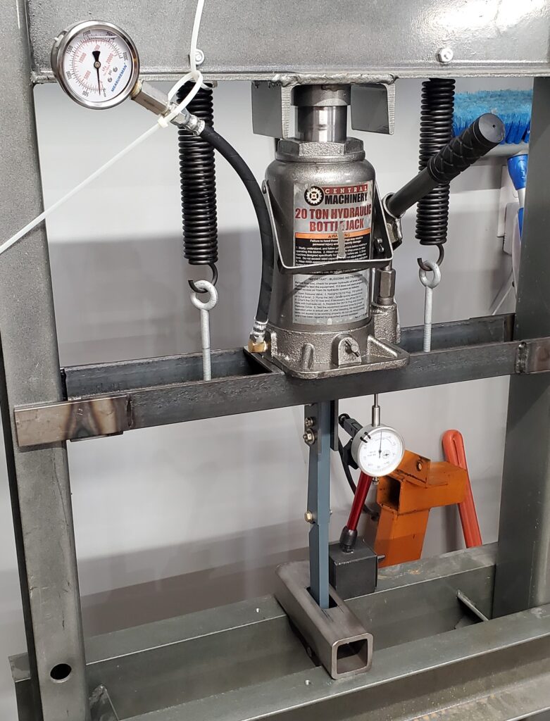
In this case I was able to load the linkage past 3500lbf and to 5700lbf without any permanent deformation. It could handle much more, in fact I’m certain that it would handle loads exceeding the tension load test results, but I wanted to only sacrifice one linkage in this exercise, so I chose to test the part to failure only in tension since that would clearly validate that the “new” bushing design was adequate. It is already known that the better material would result in a stronger assembly in compression.
Quality Improvement
I can appreciate how difficult it is to manufacture something this long with such a small joint and get a perfect alignment but the quality of the machine work on these parts would be embarrassing to me. You can see from the image below how this quality affected the overall alignment of the linkage.
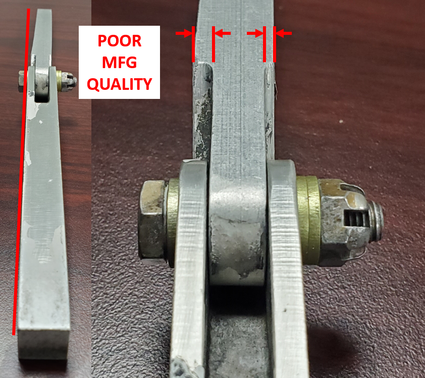
These links were made from pieces of extruded stock, only the joint, holes, and outside profile being machined, so the sides were never faced off. From what I can tell the extruded stock of GM026-1B was actually bent slightly before machining, resulting in the flats being not only offset, but also angled. This places the strut attachment point in a different, non-parallel, plane from the rest of the linkage, creating binding and weakening it under buckling loads. Obviously, I did not replicate such poor quality and even made a fixture to measure the quality of alignment of the final assembly.
I manufactured my linkage from billet blocks I had, this allowed me to face all sides and get the straightness much better. I had to machine these in a few operations in a 3 axis mill. I’m sure with a 5 axis it could be done in one or two operations at the most.
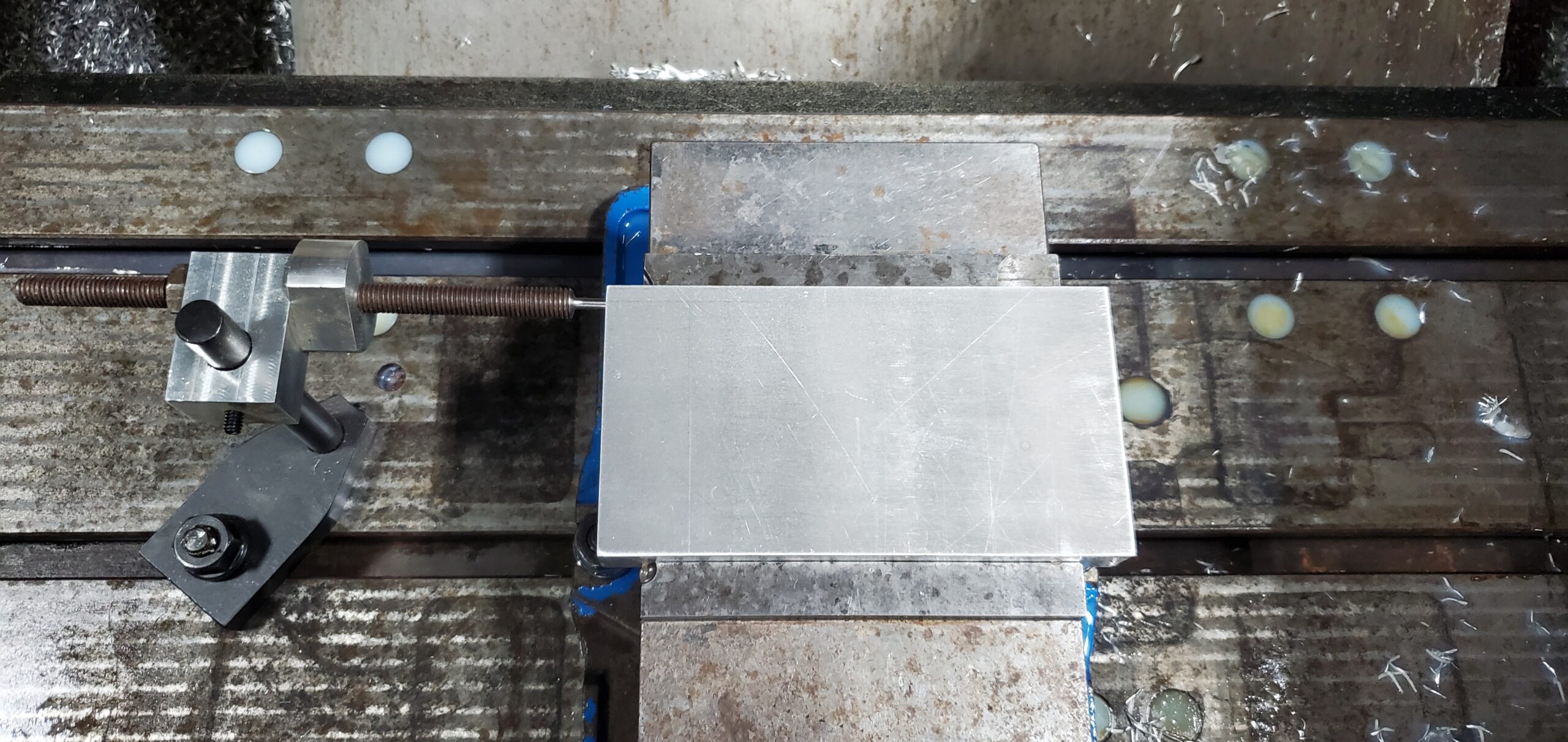
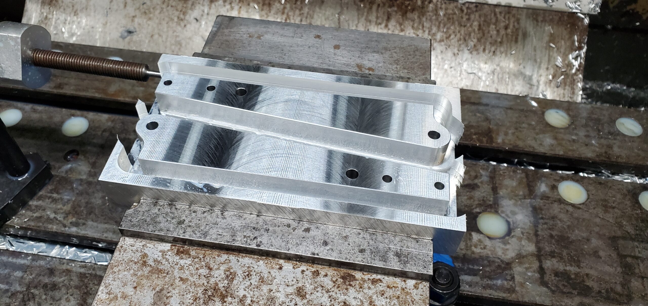
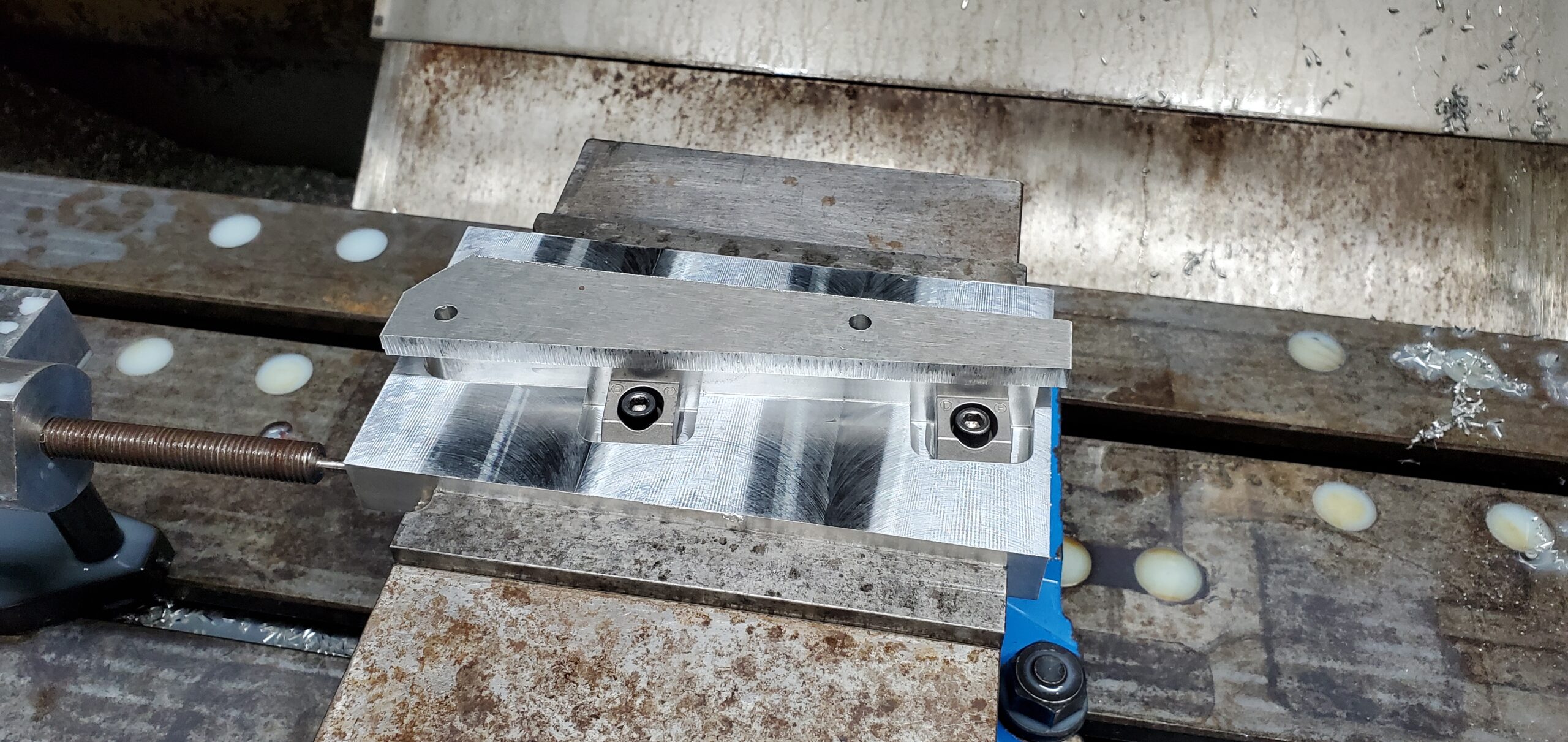
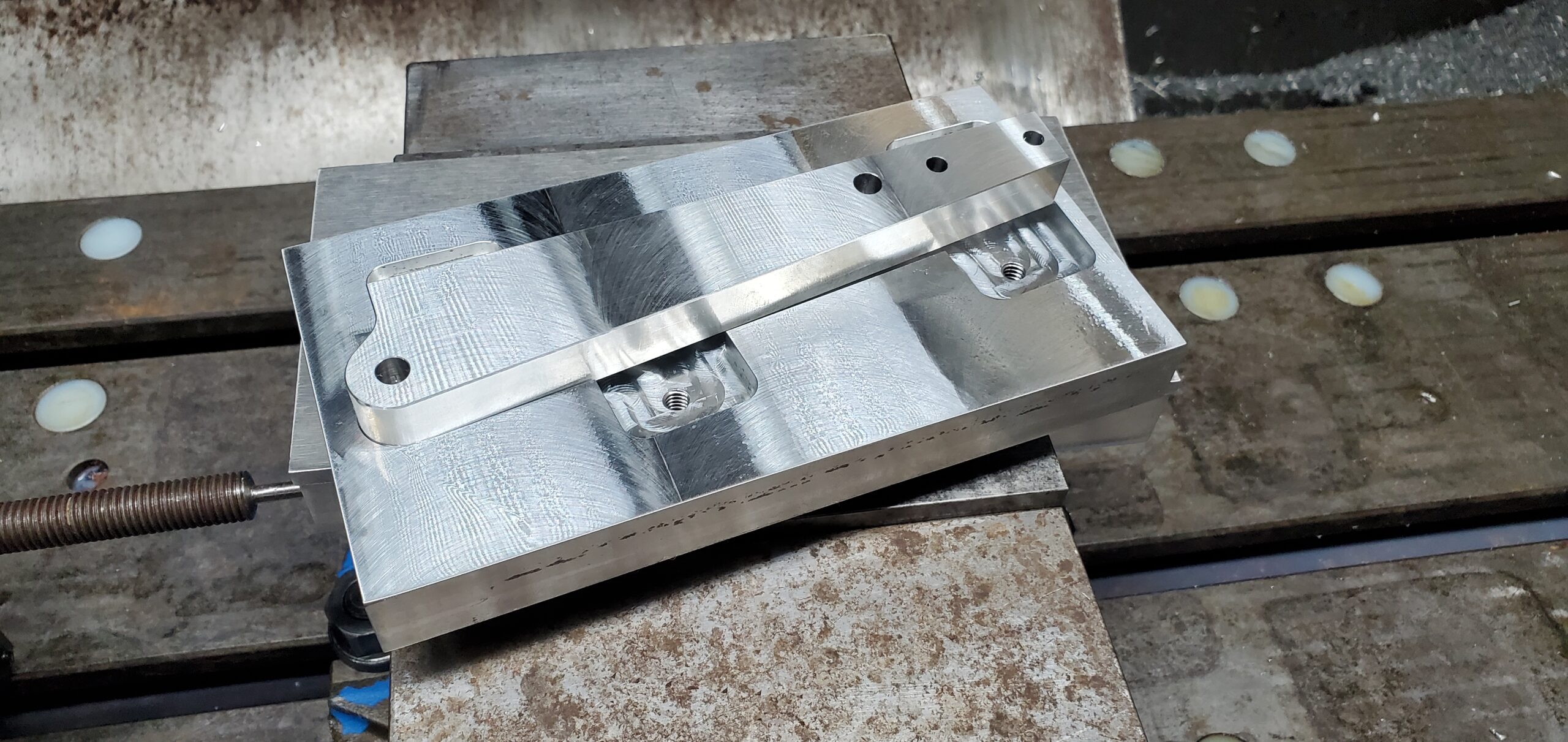
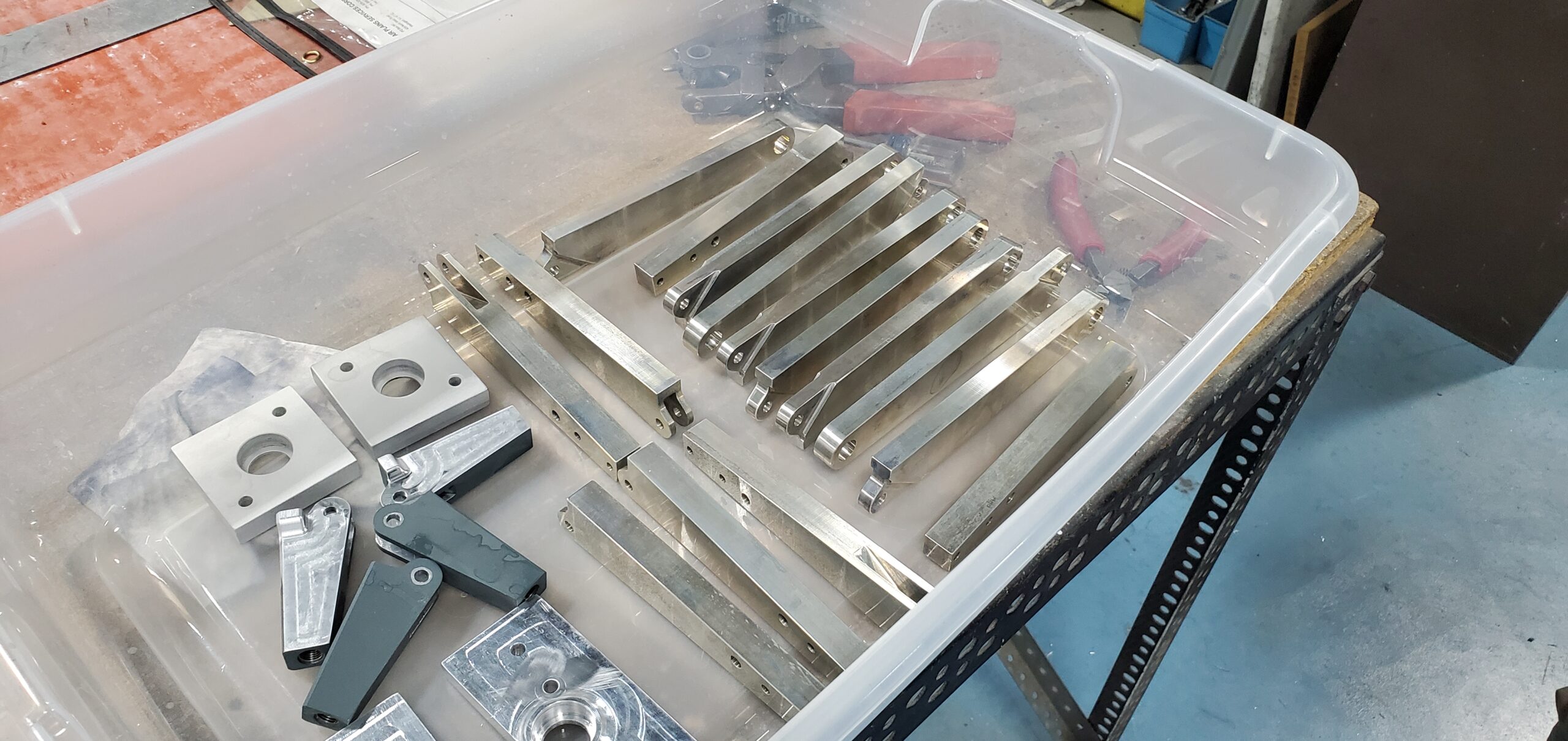
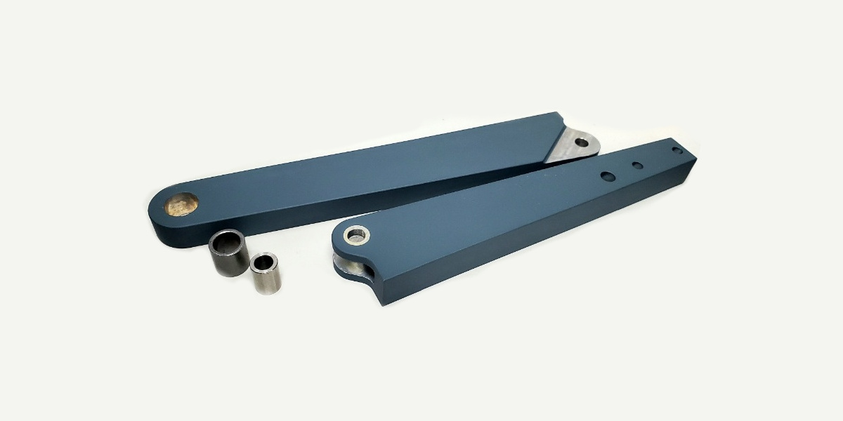
Finally, rather than anodize I choose to Cerakote my linkage. I was quite impressed how well the Cerakote held up during the load test, it did not flake off, even in the areas which were distorted. The application process is a pain however, I have done all of my landing gear parts this way and always end up spending as much time finishing the parts as machining them.

Shane:
Thanks for the great work to support the Lancair community, and this excellent writeup of the process and test results.
Well done!
Agree with Bob, I love to see the ultimate yield testing. Puts a lot of trust in a design you will absolutely depend on. Thanks again!